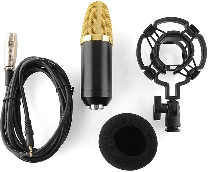
Aukeys BM700 microphone, microphone clip, cord, and wind protection.
Recently I purchased an Aukeys BM700 microphone on the web site Aliexpress.
The microphone looks like a Neumann TLM102, but for $19.18(US) I was not expecting it to perform the same as a Neumann. The price of the microphone varies depending on the day with a high of $21.13 and a low of $18.10.
Another seller has the same microphone on sale except with a silver grill and a yellow foam filter. The thing which is confusing in some of the ads is the statement NO NEED phantom power mic when it’s sold as a Pro DJ and studio recording electret condenser microphone. I don’t think you can have it both ways.
The Aukeys BM700 looks good (physically) on the web site, so I figured if it was not a good sounding microphone I could take out the microphone element and replace it with something else.
I purchased three microphones as I wanted to provide a fair review of the product, averaging test results.
Testing was performed in my home studio using a Sony MZ-R70 digital mini-disc, bench testing with a Dayton audio analyzer, and Potomac AA-51/generator and AA-51A/analyzer with a preamp. The preamp was swept prior to the test for flatness, distortion, and noise. Room calibrations were performed with the speaker and analyzer prior to measurement. Audio recordings were performed in the same location and setting. Sound files were recorded at 44.1 24 bit mono, and converted to 320kbps MP3 files for playing on the web.
The microphones were purchased on June 3rd, and arrived via China Post on June 11th, which is remarkable as the shipping was free! There was no trauma to shipping bag or contents. However one microphone did not appear to be in the original foam shipper. This microphone turned out to be dead.
Seller was contacted about the dead microphone on June 13th, and responded back with questions if I could determine why the microphone was dead. I responded the same day and told the seller since I had purchased three, and it was easy to determine the microphone was the dead and not cables or connectors. On June 16th the seller agreed to send a replacement. As of June 21st I’m still waiting for the replacement.
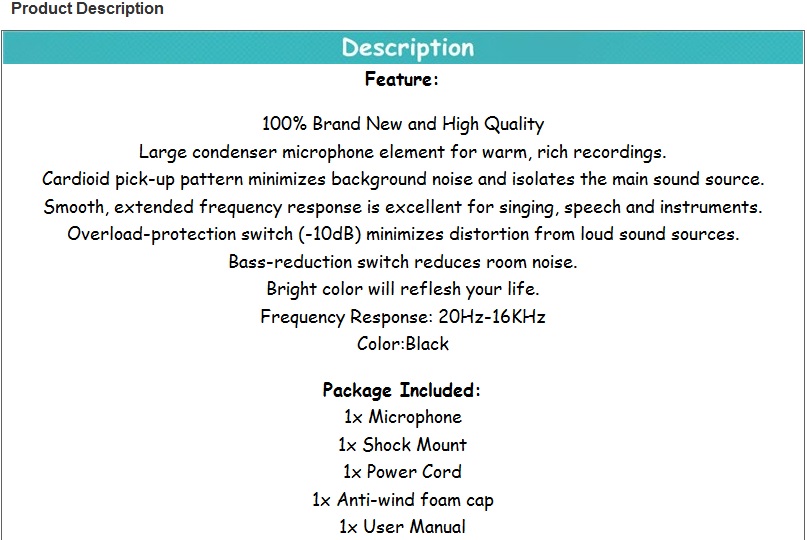
Description of product as seen on the Aliexpress web site.
The microphone pattern seems to be more of a narrow cardioid, and listening to the pickup on headphones as I turn the microphone left or right, up or down by at least 30-degrees, a drop off in level and frequency response is noted.
When the microphone is turned 180-degrees, (speaking into the back of the microphone), the level is louder that the sides, however the high frequency response is shelved from about 360 HZ upward.
When speaking into the microphone from eight inches away, without the foam wind protector, you will notice popping. Once the wind protector is on it limits the popping significantly.
The ad states, Overload-protection switch (-10 dB) minimizes distortion from loud sound sources. There is no such switch on the microphone.
The ad also states, Bass-reduction switch reduces room noise. There is no such switch on the microphone.
One would assume that a microphone with 3-pin XLR would be a balanced microphone. But the BM700 cord has a XLR at one end, and 1/8″ mini-phone plug at the other end. There is no documentation on the wiring. Specifications claim 150-ohm.
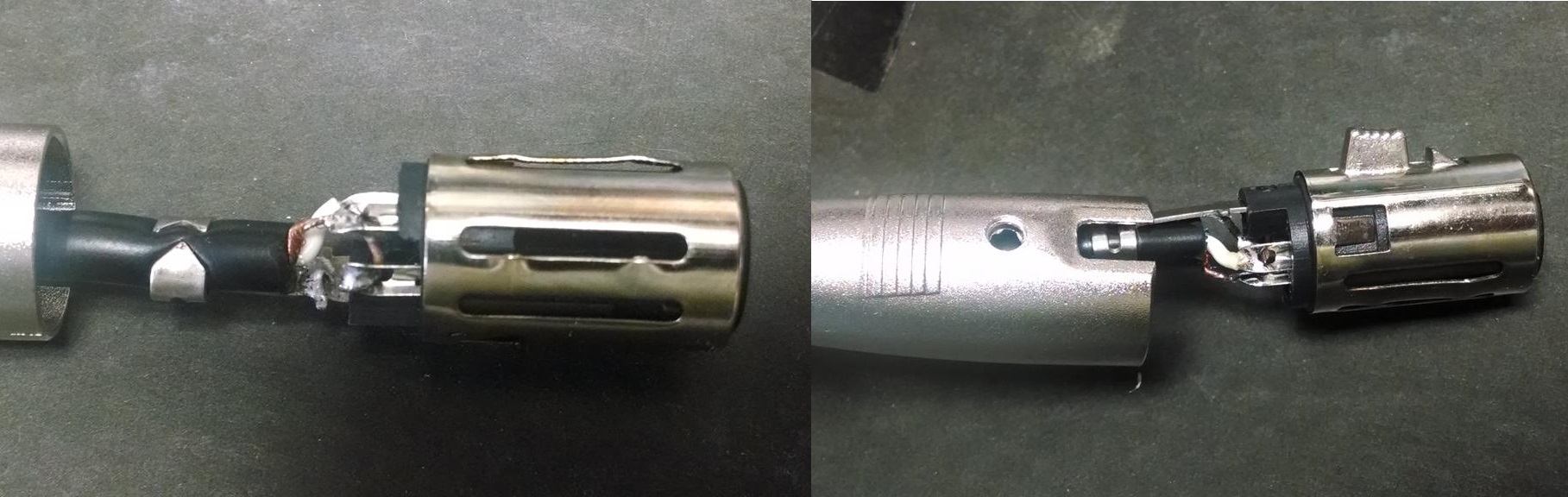
3-pin XLR which comes on end of cord furnished with BM700 microphone.
On the XLR end; pin 2 is the hot wire, while pins 1 and 3 are shorted together with the braid of the shield of the cable. On the 1/8″ connector side; ground is the shield, while tip & ring are the hot side, connected to pin 2 of the XLR. This seems to work well on my Sony minidisc recorder. However, since I could not find a way to take the microphone apart, verification of a balanced 150-ohm output from the microphone can not be verified.
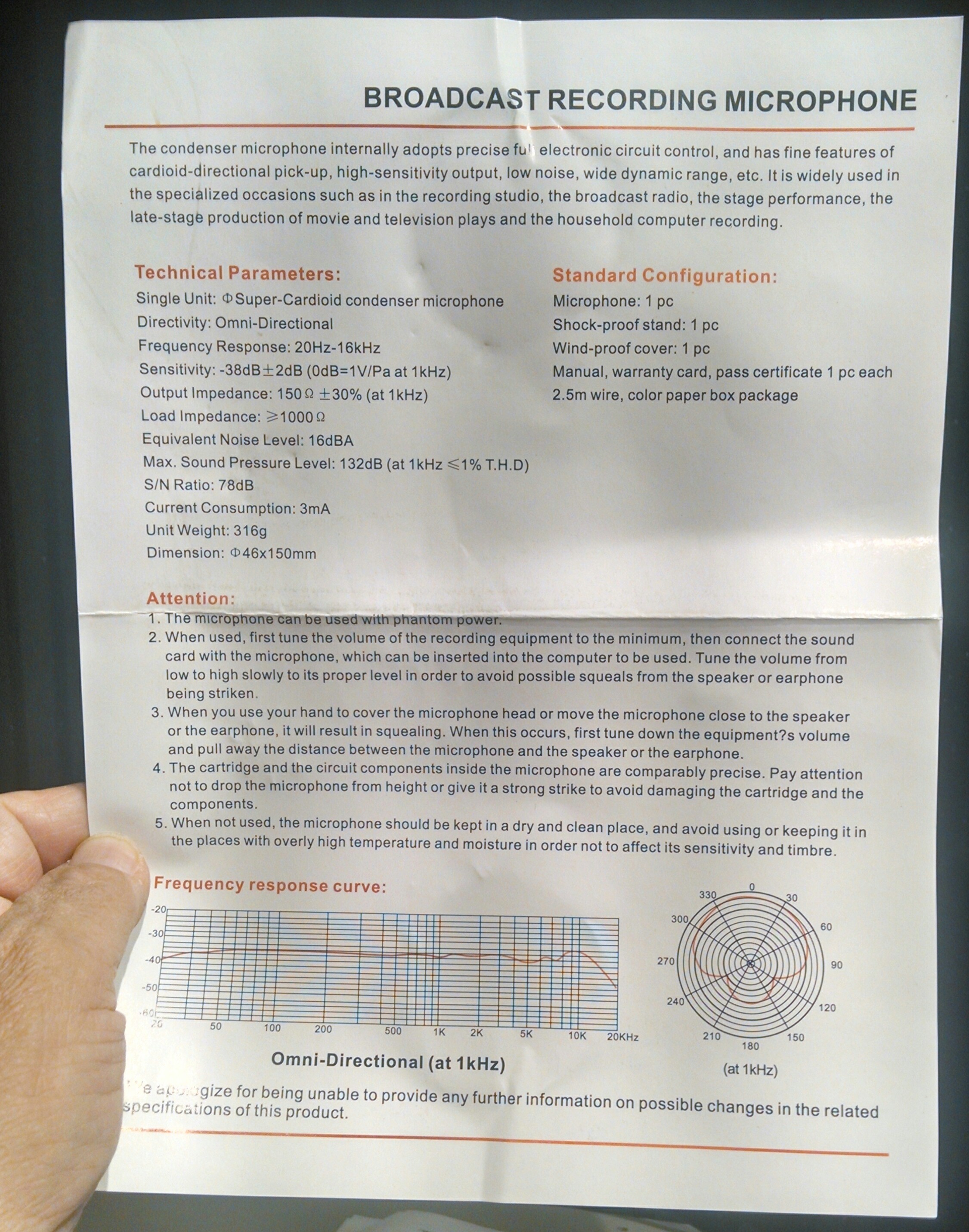
BM700 Specification Sheet
The specifications state that the buyer receives a “user manual”, In reality the manual is one sheet of glossy paper printed single side.
Specifications state frequency response of 20 Hz to 16 KHz, with a sensitivity of -38 dB, +/-2 dB. The stated output impedance is 150-ohms, with a load of approximately 1,000 ohm. In looking at the graph at the bottom of the sheet you can see the stated pattern of the microphone, as well as the claimed frequency response. This response is somewhat misleading as I found depending on the azimuth and elevation of the microphone, with respect to the sound source, different values would peak and fall. For the most part I found the BM700 provided a boost in an octave centering around 5,300 Hz. You can hear the difference when compared to an Electrovoice RE20 microphone.
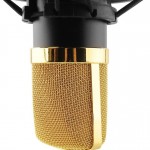
BM700 microphone grill
The microphones appears to be well made and machine tooling is clean. The gold grill of the microphone is especially bright and clean. The barrel is a non-reflective dull black. The male XLR is recessed into the bottom of the microphone with only 3/16 of an inch of silver connector showing. The pins for the XLR connector appear gold in color.
When looking into the grill I can see the microphone element which appears to be about one inch in diameter. There is no silk or cloth between the grill and the microphone element to prevent dust or foreign objects to come in contact with the microphone element or to prevent pops from speech. If I could take the microphone apart I would add this to the inside of the screen to prolong the life and usefulness of the microphone.
Examining the microphone body I can find no screws or indication how it’s put together. For the moment I’ll assume it’s either a tight threaded barrel or press fit.
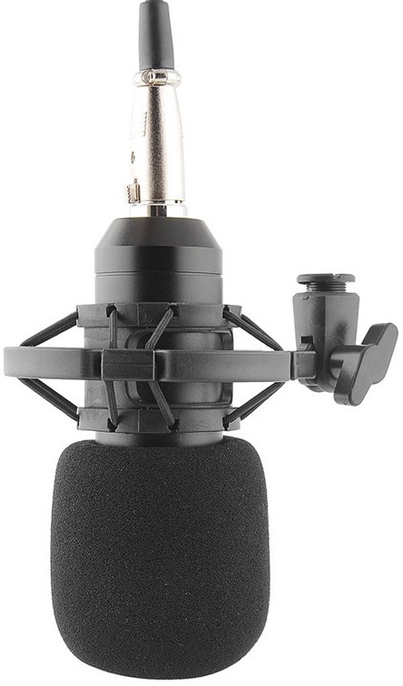
Side view of microphone with microphone mount.
The microphone comes with a mic stand holder. The microphone is slid in, (somewhat tight), up to the grill ring, and is held in place by friction.
The tooling of the stand mount will accept both the U.S. standard microphone stand and European. Standard US mic stand thread is 5/8-27. The smaller European-style thread is 3/8-16. An adapter for the smaller European mount is furnished.
The microphone mount is not made out of metal, but it appears to be a hard ABS plastic with stretch strings to cushion the microphone. An adjustable wing-nut allows for positioning of the microphone in a range of 190-degrees up and down. I did notice some “slop” in the mount when the wing nut is loosened for elevation adjustment. It appears the hole for the screw is oval, rather than round. It does not impede the use of the mount, nor make it unusable, but it could have been machined better.
TESTING
Testing the microphone was very difficult. Depending on the axis of the mic in relationship to the test speaker, I would get different results.
The mic claims to have a response of 20 Hz to 16 KHz, but I found the low end lacking in many cases, and the high end rolled up 2 dB starting around 2,300 Hz.
Signal to noise ratio claims to be 78 dB, but my tests had it more in the range of 66 dB.
How does it sound? Let’s compare an Electrovoice RE20 microphone, (broadcast standard), to the Aukeys BM700. When recording these files I did not make any changes to the sound level, or equalization.
- Speaking into the front of an Electrovoice RE20.
- Speaking into the front of a BM700.
- Speaking into the side of a Electrovoice RE20.
- Speaking into the side of a BM700.
- Speaking into the back of a BM700.
- Pop filter test of BM700.
CONCLUSIONS
This is by no means a “broadcast” or “professional” mic, nor would I use it for crucial sound recordings.
For the cost, $19.18(US), I would find it useful for my computer, recording speech on my mini-disc, or perhaps with an interface it could be a nice microphone for my amateur radio transceiver.
As you can see by the pictures the microphone is very good looking.
The price is justified for the body of the microphone. If I can find a way to take the mic apart, I think I’ll replace the microphone elements with my own professional ribbon or dynamic elements.
I’ve had a difficult time communicating with Aukey to get a replacement or refund on the microphone. This is not unusual when dealing with a seller who does not speak English as their primary or secondary language. Based on the seller’s web page I also felt they could be a seller or general merchandise, and not someone familiar with electronic equipment, (such as professional microphones). Just be aware of this when you make your purchase.