
As I work on my home studio I’ve run into level problems in the rack. My rack is not crooked, but my levels are! Anyone who has shot excessive level into an electronic device knows that bad things happen. Most of us don’t always stop to check levels before recording. You patch, hit record, and start recording, only to find out during playback that the recording is distorted.
Levels are measurements in decibels (dB) and be considered either as a power or as a voltage. The level in decibels is 10 times the logarithm of the ratio of two power levels. There are three ways to measure;
- dBm: decibels or dB referenced to 1 milliwatt (.001 watt)
- dBu or dBv: decibels or dB referenced to 0.775 volt (dBu is more commonly used)
- dBV: decibels or dB referenced to 1 volt
I maintain a standard in my home studio of balanced 600-ohm audio at 0 dBu at all inputs/outputs on my patch bay. By doing this I don’t have to change the recording level on the machine based on the source device selected. Some older tube devices have zero reference levels of +4, +8, or +10 dB. I have even seen +12 dB outputs on some old 1940s equipment. The mission is clear. I need to have the level decreased to satisfy my house standard. The solution is the “H” Pad.
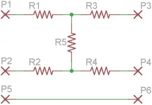
An “H” pad is simply five resistors made in the shape of an “H” laying on its side with the values calculated to achieve a specific loss of signal while maintaining proper impedance. In the case of coming out of a tube compressor with an output of +8 dBu, and needing to have 0 dBu appear at the patch bay, the solution is to calculate for 8 dB of loss.
I hook up the equipment’s output to pins P1, P2, & P5. P1 is +, P2 is -, and P5 is ground.
From the pad, pins P3, P4, & P6, to the patch bay top row. Pin P3 is +, P4 is -, and P6 is ground.
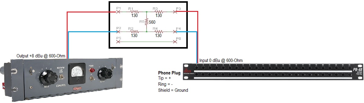
What about ground? Without getting into a big debate, I’ve found the most practical solution in high RF/noise areas, and to prevent ground loops, is to float the ground at the output end and attach it at the input. Therefore, all inputs to my patch bay, (top row), are grounded.
From the chart below, and looking at the schematic of the pad above, we find the values of the resistors.
We need to decrease the level by 8 dB so R1, R2, R3, and R4 are 130-ohm, and R5 is 560-ohm. A caveat here; the assumption is that your output equipment is 600-ohm, and the input of the patch bay is 600-ohm. (Click on the chart to enlarge it and print).

H Pad Values
The P.C. Board is very small and measures a whopping 1.50″ (38.1mm) x 11/32″ (8.731mm). It was made small for a reason. It will fit inside of equipment, or inside of a Switchcraft barrel connector. Most of the time I simply attach this to the output, securing the pad to the back of equipment with stand-off posts, and then run a wire to the patch bay.
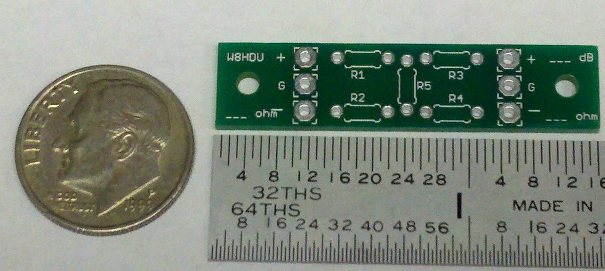
The bottom is where you solder carefully. You need to use a soldering pencil with a very sharp point, thin solder, and solder at approximately 675-700 degrees.
The top of the board has the outline of the resistors. The proper resistors to use would be ones like the Xicon Metal Film Resistors which have a diameter of .07283″ (1.85mm), and a body length of .137″ (3.5mm). Available from Mouser Electronics you would want (4) 130-ohm resistors, and (1) 560-ohm resistors. These would be p/n: 270-130-RC, and 270-560-RC.
The 1/4 watt version of these resistors are tight on the board and one end needs to be raised up, but will work in a pinch. The 1/4 watt versions have a diameter of .0984″ (2.5mm) and length of .2677″ (6.8mm). They would be p/n: 271-130-RC, and 271-560-RC.
Both sides of pad PC Board.
A small hole at each end provides a way to mount the board using a 2-56 screw and spacer, (Keystone p/n: 1797C), also available from Mouser.
Here is a completed 3 dB pad which is ready to be installed. Note the size of the PC Board in relation to the dime.
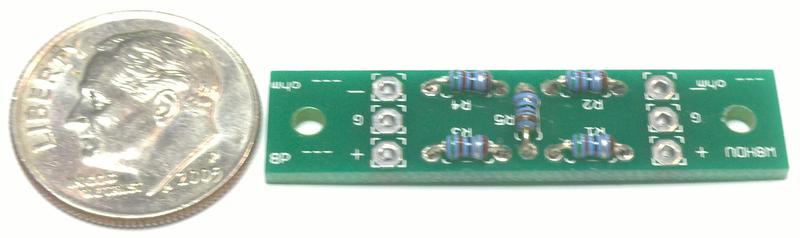
Complete 3 dB pad
This pad will be installed inside the back panel of a tape machine, so the machine remains original spec, but the audio handed off to the patch pay and other equipment is at my required 0 dBu level.
Note: You don’t have to use a PC Board, although it looks better. But if you’re careful, keep your leads short, and use some electricians tape to prevent leads from shorting against the cabinet and other equipment, you can install a pad inside just about anything.
Thanks for a really good tutorial on how to pad audio. This was very helpful to me. Many of the devices in our radio station are still running on balanced audio, and sometimes the feeds are too hot. This posting was very helpful to me.