
This project came about when I tried to find a remote control panel for a Panasonic video tape recorder at work. I soon realized that other machines, even my own Otari MX5050B-II didn’t have a way to be operated from across the room. Yes, Otari made one, but I couldn’t find one that wasn’t beaten up or buggy. I decided to build my own remote control.
While in the design phase it occurred to me the control could be used on other tape machines. For this reason I decided to make the button PCB generic. Along with making it simpler from a design standpoint, it also allows consistency with the look of the panel. I don’t know about you, but having multiple remote control boxes and panels sitting around my room frankly makes the control room look trashy. The button panel furnishes LOW logic from the buttons, and LEDs light when the corresponding pin is grounded.
Since the logic of an Ampex, Tascam, Marantz, and Teac are all different, it’s easier to have a button control interface to the command logic and status. To obtain status I need to “hack” the machine for signal states to relay back to the buttons. For example; a Tascam A3300SX-2T does not have lighted remote control capability, but we can hack the machine so when the Play button is depressed, it lights up the “play” button on the panel.
The control interface uses dry contact relays to isolate the button presses from the machine. The relays are quieter than the ambient noises generated by the machine going into a modes.
BUTTON PANEL
Here is the button panel schematic.
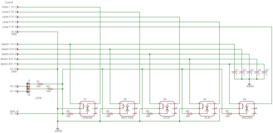
Schematic for button assembly.
The button PCB uses five Veetronix push button switches. These were chosen due to their feel, and proven longevity in a production studio environment. These are the same switches found in many broadcast video switchers. Four switches use .72″ square caps, and one switch (stop button) is a .72″ x 1.45″ rectangle cap. Each switch may be lit with an LED or incandescent bulb. There is the ability to have two auxiliary LEDs to indicate power and record enable. These are powered from the five volt buss and drawn to ground to light the LED.
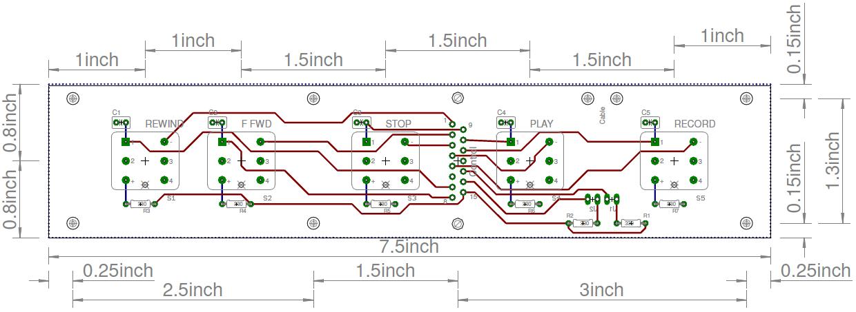
PCB layout without ground plane.
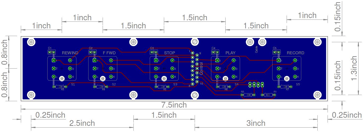
PCB layout with ground plane. (blue is back, red is top)
The board measures 7.5″ x 1.6″ (19.05 x 4.05cm). A male DB15 is the interconnect device between the board and cable. The board is mounted to the back of a rack panel using 1.125″ hex standoffs. One set of standoffs connect to the frame of the DB15 to give it rigidity.
Below you see a 1RU rack panel which holds (2) remote control boards. The holes you see next to the buttons indicate remote ready, and record enable.

1RU panel for (2) control panels
The “Play” button uses a green lens, the “Record” button uses a red lens. The rest of the lens caps are white. The lettering is produced by printing on an overhead projector (clear) sheet with a desk-jet, and cutting the plastic sheet so the word is centered, and dropped between the lens and the lens backstop.
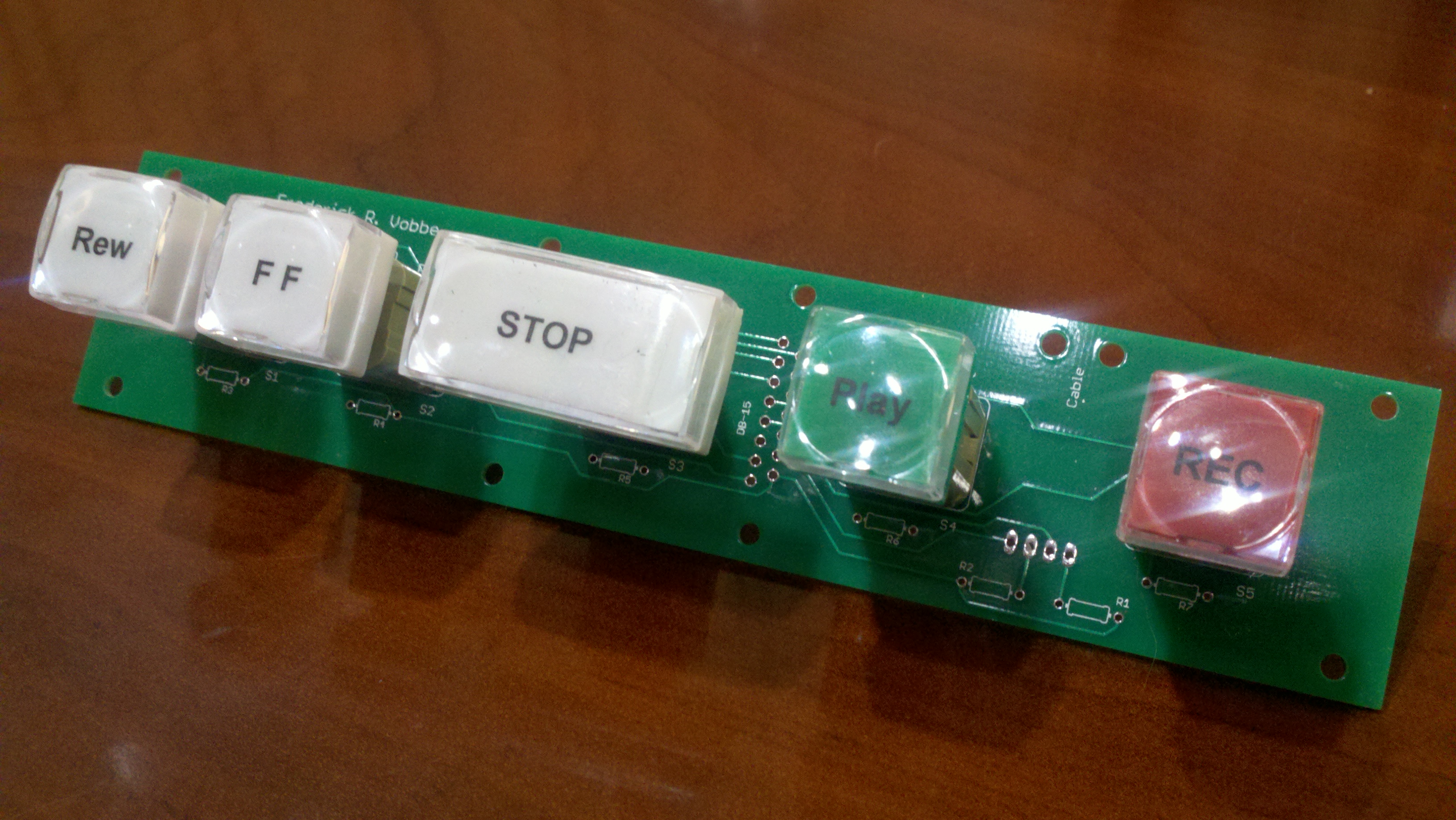
PCB layout with Veetronix switches mounted on PCB
When the board is assembled into the panel it looks like this.
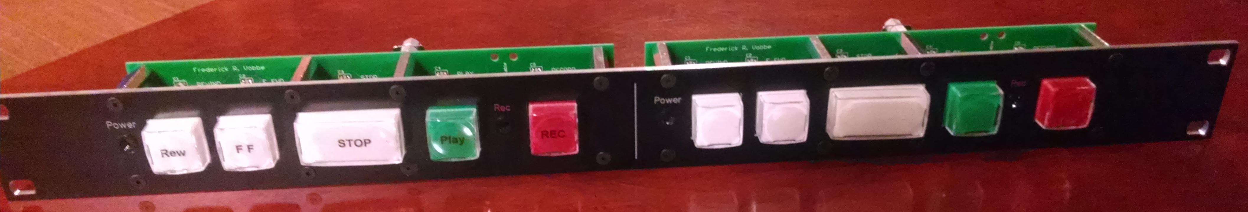
Front of control panel. Left side is labeled, while right side is not.
Note: The power and record enable LEDs are not yet in this panel.
On the back side of the PCB is a male 15-pin DB connector. Using a 15 conductor cable with a female DB connector, this allows the panel to be installed, then plugged in, and attachment screws tightened to keep the cable from falling out.
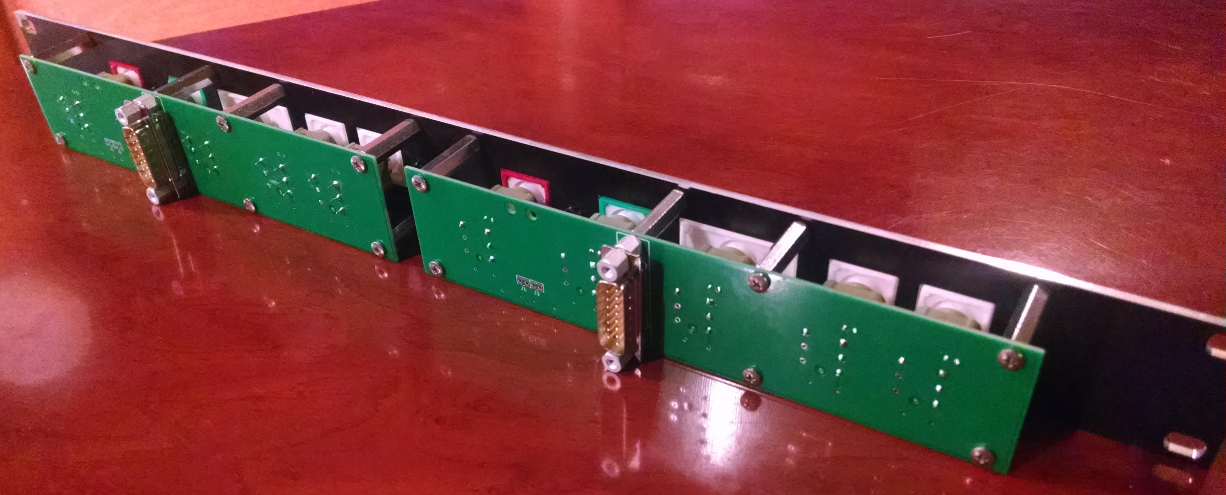
Control Panel (back side) – Unfinished
As pointed out earlier, the control panel is generic, and contains (5) switches which contain LEDs to light the button, and (2) LEDs for “power” and “record enable”.
In part two of this article I’ll talk about interfacing machines, and how to deal with machines which have no provisions for mode status.