
HyGain Model VB28FM
Growing up with depression era parents and grandparents I learned a good lesson. Don’t be quick to discard something which might have value. Something broken can be fixed, and with some sweat-equity you can realize something expensive for very little money.
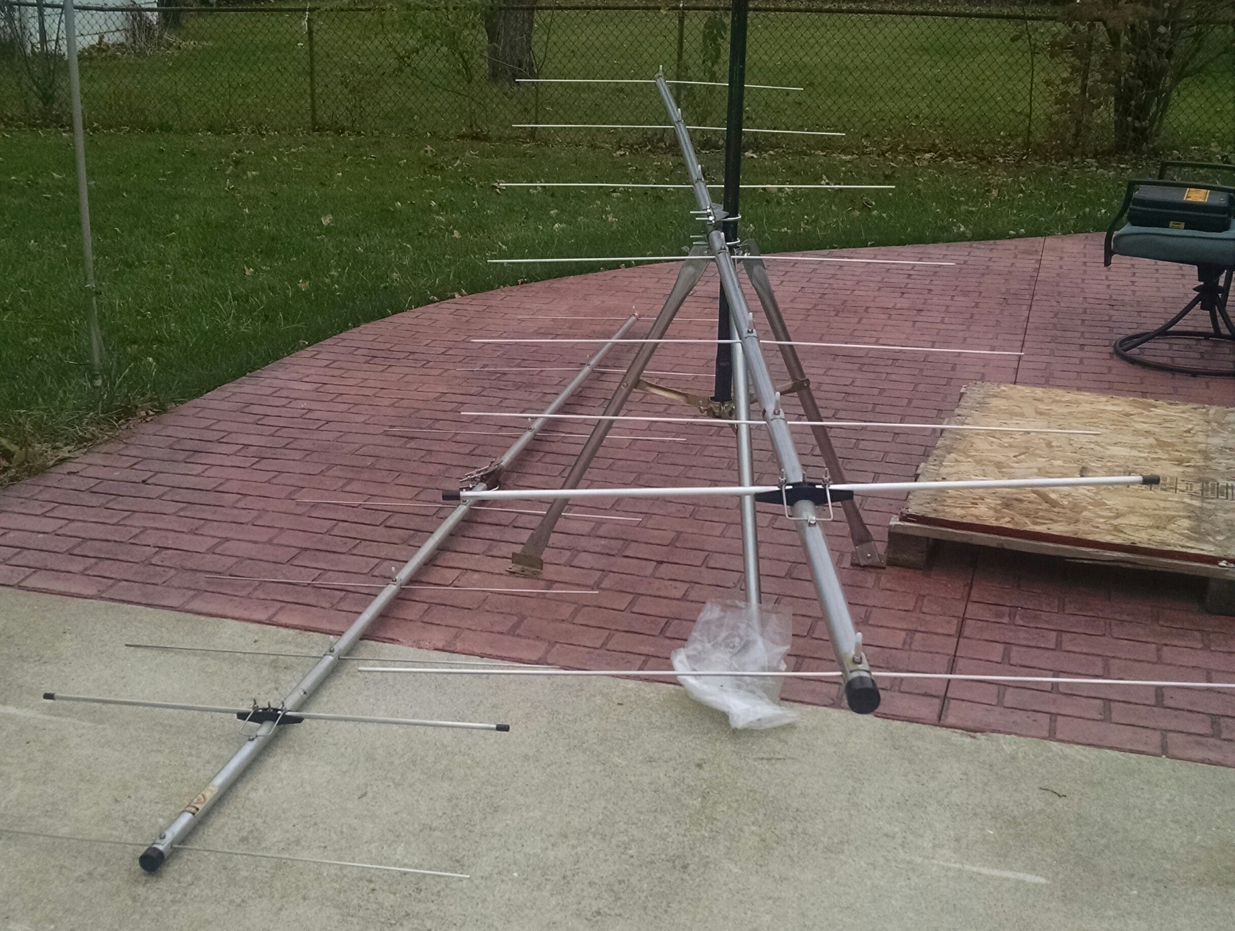
Recently I found a pair of HyGain VB-28FM antennas. The ham who had them was not happy with them. These antennas had been up on his tower since the mid 1980s, were quite corroded, and in sad shape. He was tired of 2-meter FM, (working distant repeaters). He concluded the antennas were no longer of any value to him and he wanted them gone.
I took the antennas because I love to experiment and refurbish antennas. And contrary to his assumption these are “FM only antennas” these will work great for CW and single sideband in the 144.00 to 144.30 MHz range.
INTRODUCTION
The HyGain VB28FM has been around for a while. The VB-28FM is still in production and a manual for the antenna can be found simply by Googling “hygain vb28fm“. I’ve found VB28FM antennas for anywhere between $69.95 to $100 at various web sites.
The VB28FM’s bigger brother is the HyGain VB-214FM. The little brother is the VB-25FM, and little sister is the VB-23FM. The design of each antenna similar, but each model has a different number of elements, and of course, gain.
The VB-28FM’s stated frequency range is 144-148 MHz, which encompasses the whole 2-meter band. It’s further stated that the antenna is good for 4 MHz bandwidth with a maximum VSWR or 2:1. I did find the original antenna slightly less bandwidth than claimed.
The gain of a VB-28FM is 14.0 dBi, or 11.8 dBd. The front to back ratio is 20 dB. The stated maximum input power is 250 watts continuous, or 500 watts PEP. Half power beam width is 43° in vertical operation, or 36° in horizontal operation.
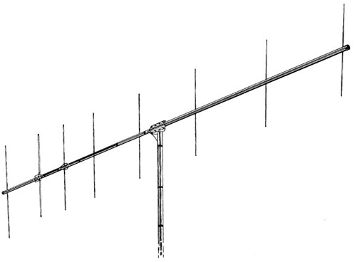
HyGain VB28FM Antenna
The VB-28FM has 8 elements, and is 148.75″ long. The widest element, (the reflector, tip to tip), is 40.250″.
The antenna weighs 4.25 pounds, and needs about 80″ of turning radius when operating them in horizontal polarization. In reality you should have more space to limit VSWR reflections.
When installing a second VB-28FM in a stacked arrangement it’s recommended that the antennas are placed 1 wavelength apart at you operating frequency, which should also be the best match.
A good formula to use for spacing in inches is ((300/f)x39.3637), where f is your ideal operating transmit frequency. Keep in mind you’ll have to make a 75-ohm power divider to feed both antennas in phase. I’ll explain how easy this is later.
FIRST THOUGHTS
Element Attachment
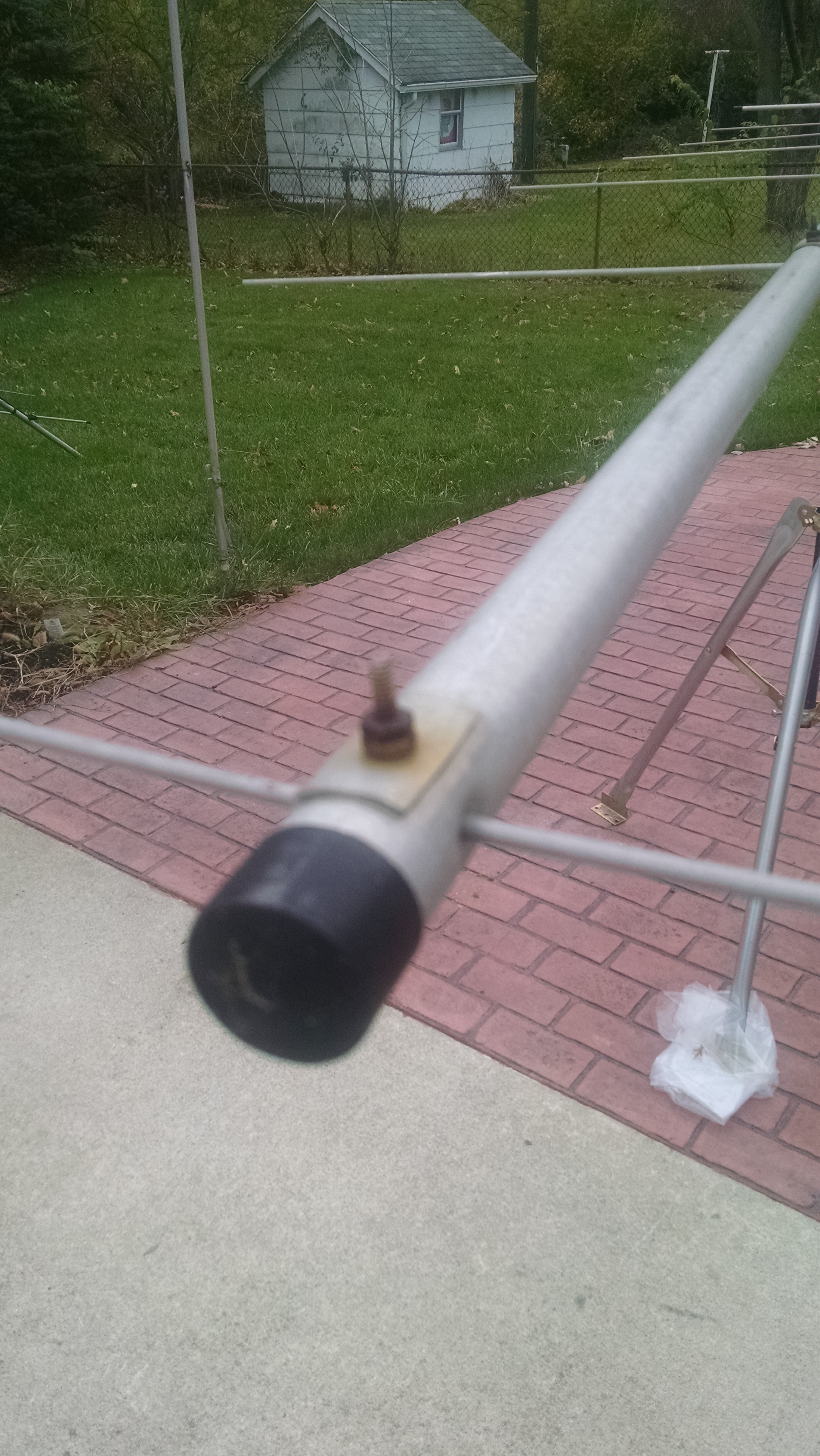
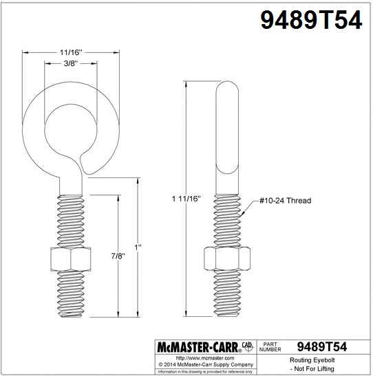
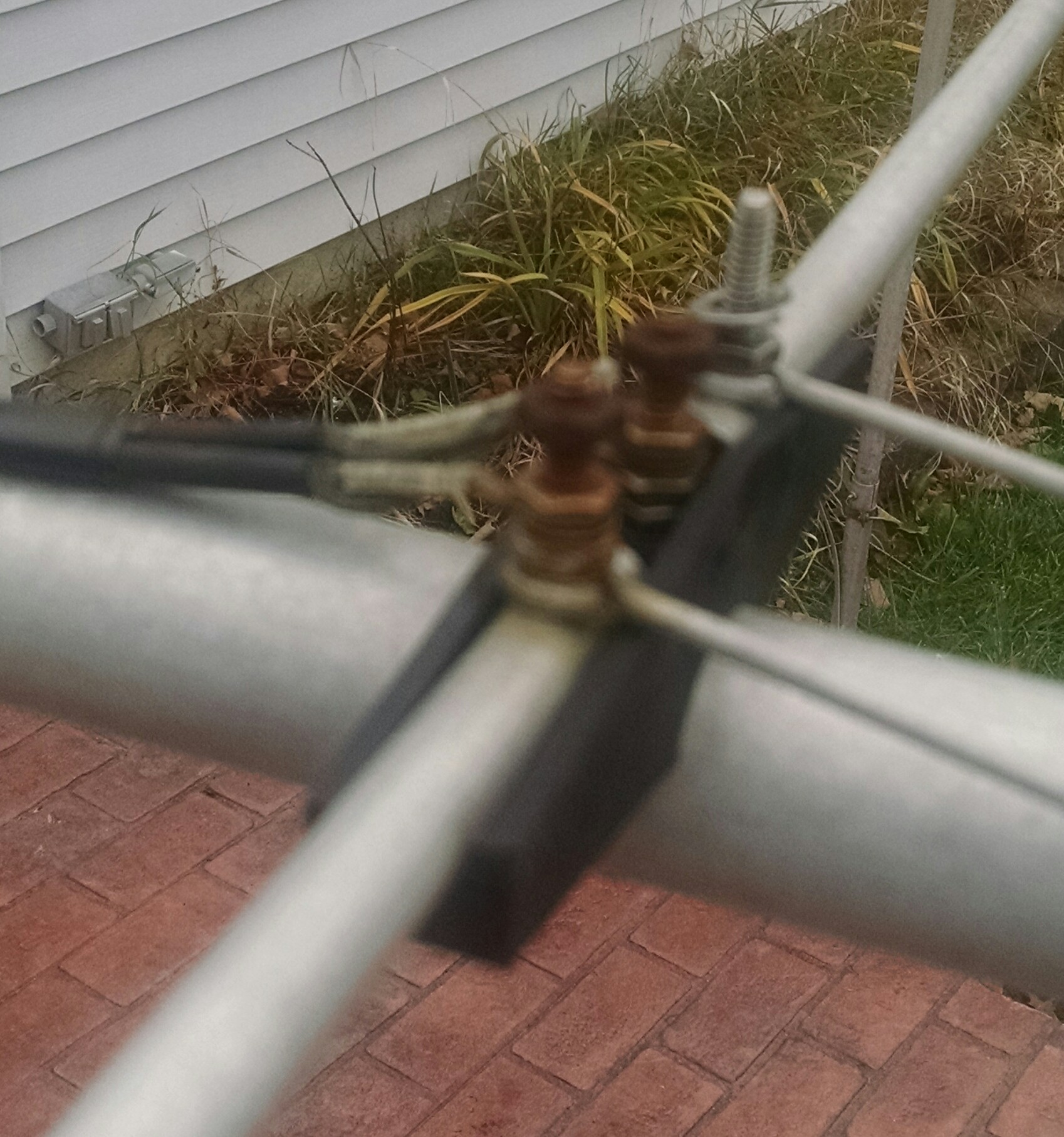
The overall mechanical design of the antenna is good, but could use some improvement. The elements are held in place with a routing eyebolt.
An element goes into the boom, through the eyebolt, and exits the other side. The eyebolt is then tensioned up to hold the element in place. As you can see from the picture the existing bolts were quite rusted. The instructions call for the eye bolt to be attached using (2) 10-24 nuts torqued together.
I found over-tightening of the nuts can bend the element. Instead of it being straight across the boom at 180-degrees, it may be 177-degrees. Once the element can not slide back and forth inside the boom it’s tight enough. There is no need to over-tighten.
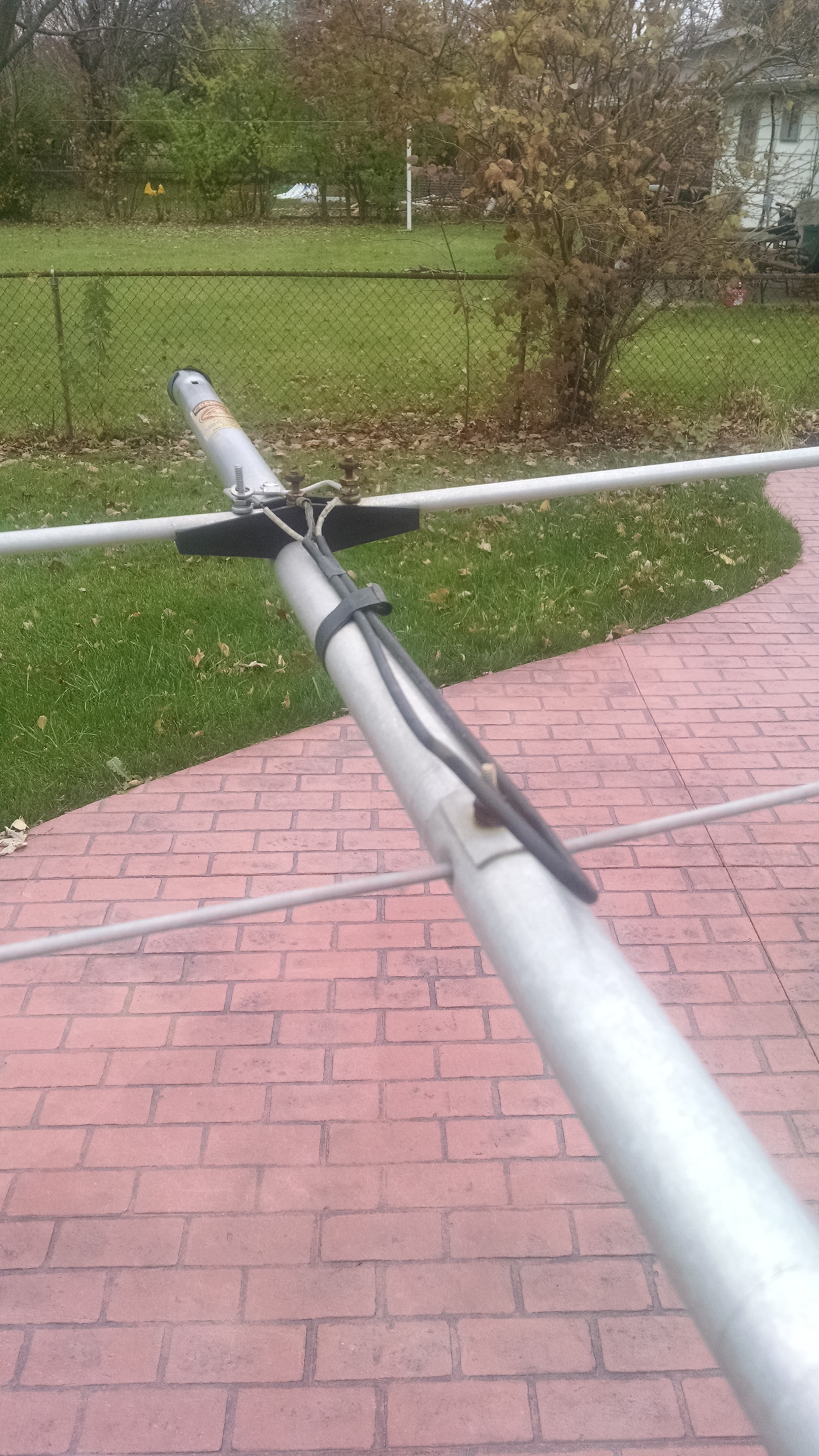
Feed-point of the antenna
The feed-point of the antenna is a “wire lug” connection with the shield of coax going to the boom, and the center conductor feeds one of the driven elements.
The signal is then fed to the second driven element using a 1/2-wave section of RG-58/AU coax. A “hairpin” attached to each driven element and grounded to the boom of the antenna.
Although the picture is blurry, you can see the connection was very rusty from the hardware, and the coax was basically rotted out due to being exposed to the weather.
RESTORATION
The first thing I did was to disassemble the whole antenna and straighten out the elements which were bent. The elements were scoured with steel wool to remove corrosion. One of the boom sections had a slight bend at the first director but it was not enough to cause any concern.
Eyebolt
I replaced all the eyebolts which held elements in place, (along with the zinc nuts and washers). To make these antennas right, stainless was the only way to go.
I found stainless steel, 10-24 Thread, 1″ Shank, 7/8″ Thread Length Routing Eyebolts at McMaster Carr. They were p/n:9489T54 and cost $7.55 per pack of 5. You will need at least three packages for the VB28FM.
I also replaced the (2) 10-24 zinc nuts with (1) type 316 stainless steel nylon-insert Hex Locknut. These were available from McMaster Carr in packs of 100 for $9.42 and are p/n: 90715A011.
The type 18-8 stainless steel internal-tooth #10 lock washer is available in packs of 100 for $3.63 and are McMaster p/n: 91757A107. I typically buy 100 packs as I know I’ll need more hardware later for other projects.
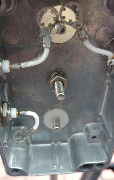
Feed point of the antenna
This brings us to the feed point, which I feel is a critical factor in antenna design, but was the most compromised in this antenna’s construction and design. The hardware was rusted, and the connection depended on bare wire attachments of the transmission line and the phasing cable. This may be OK on a TV receive antenna, but the RF connection to the antenna should be a standard UHF or Type-N. The phasing harness would have the same integrity and be protected from the elements.
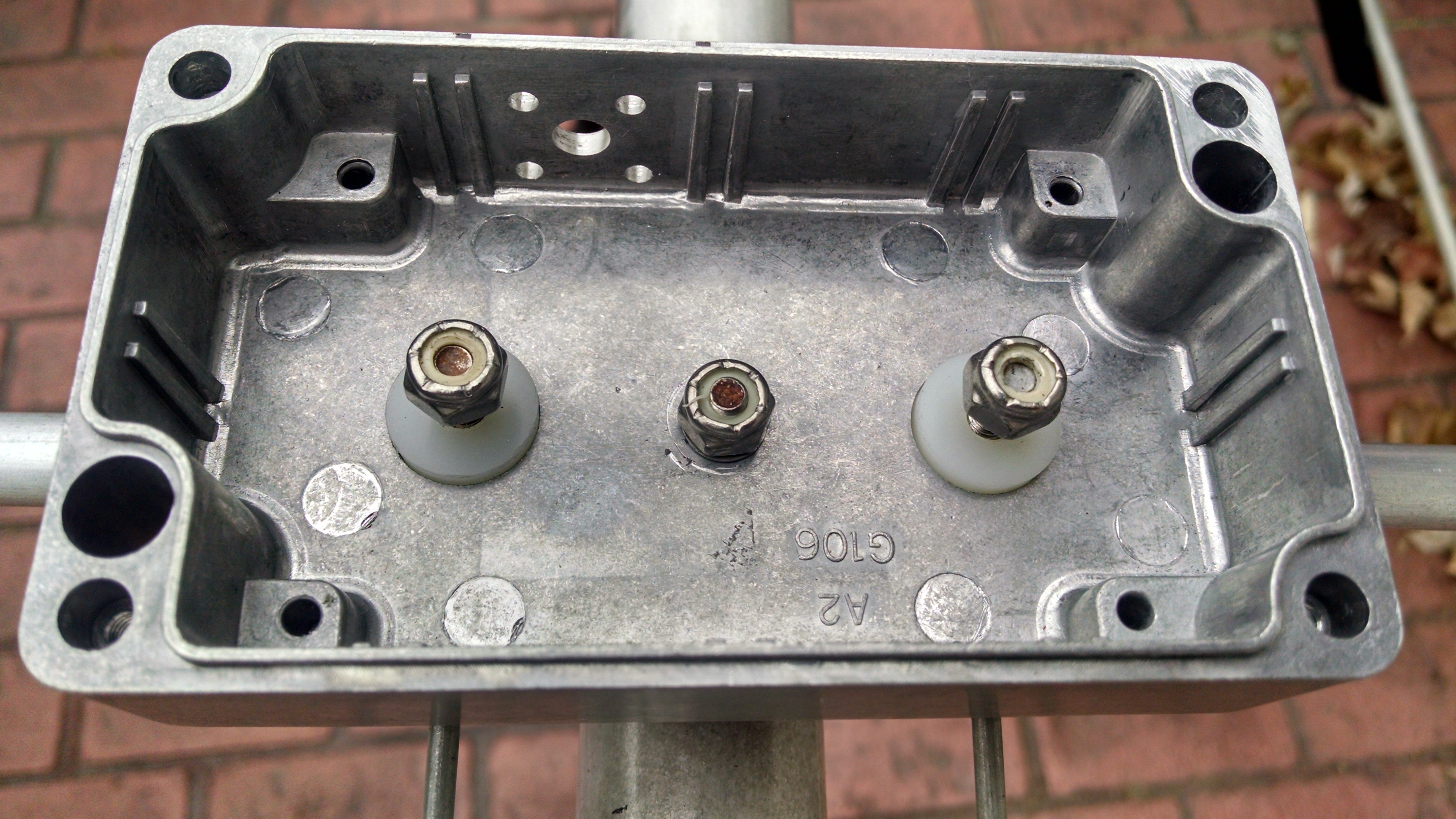
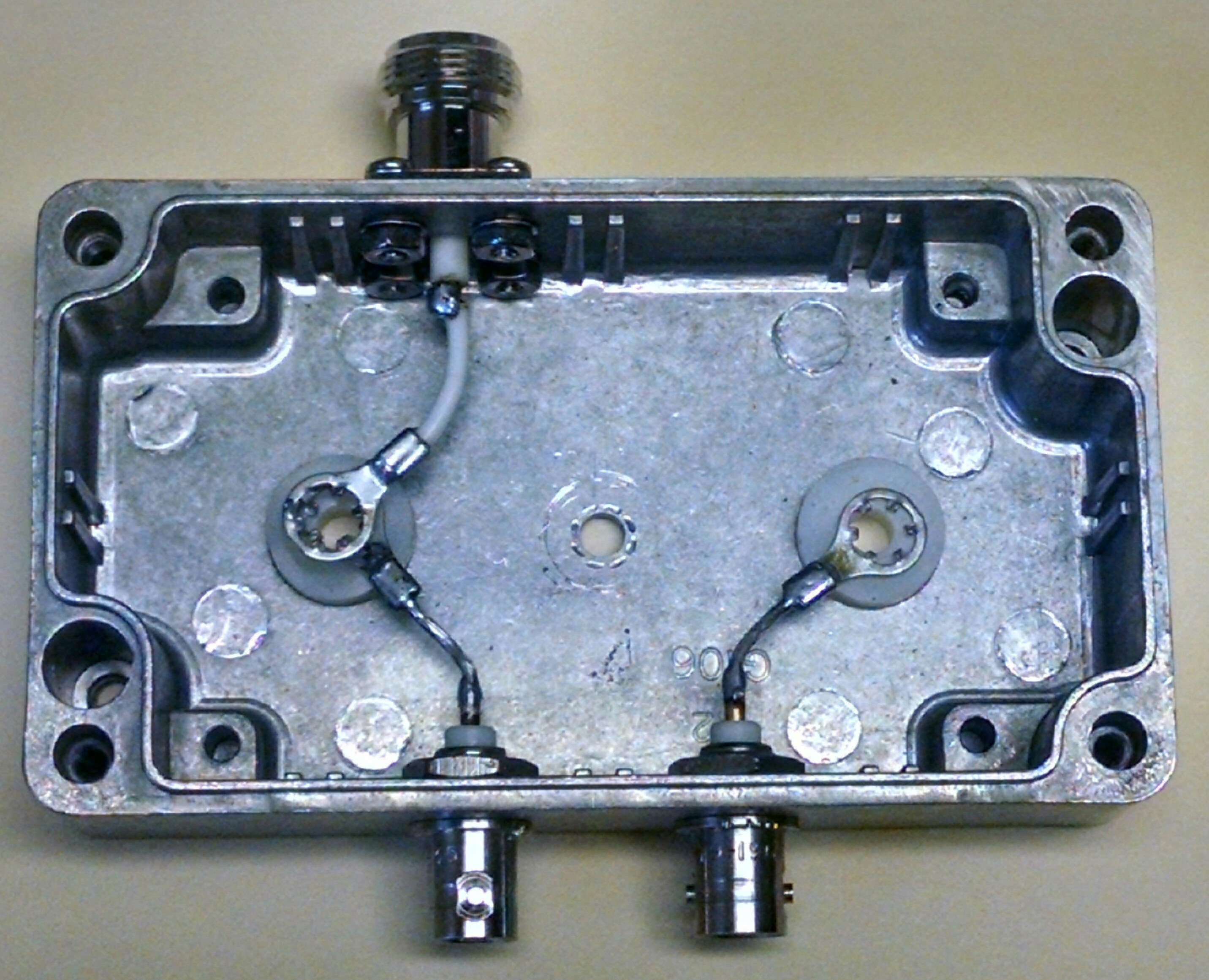
RF Connection Box
I decided to standardize with a small outdoor rated, sealed aluminum box using a Type-N connector for the RF input, and (2) BNC connectors for the phasing line.
To insulate the antenna connection points from the box, nylon unthreaded spacers, 5/8″ OD, 1/4″ long, and tooled for a #10 screw were used. These are McMaster Carr p/n: 94639A170 and were $8.24 for a pack of 25. The box is a Bud AN1302, Natural NEMA 4.53 x 2.56 x 1.18″. It’s Mouser p/n: 563-AN-1302 and cost $9.40.
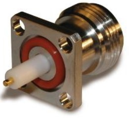
Amphenol 172117 Type-N
Because the profile of the box is small, (to limit wind load), I had to use an Amphenol 172117 chassis connector. It is Mouser p/n: 523-172117 and costs $5.53.
The connector Is designed to mount to the outside of the box with one penetration hole to feed through the RF, and four connection points. (4) #4-40 stainless screws with stainless washers and nut hold the connector.
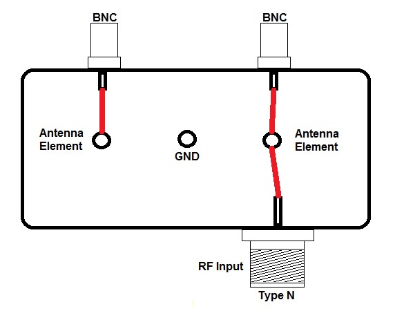 The feed is rather simple. The RF input connects to one element, and then exits to the phasing line. The phasing line is connected to (2) BNC connectors on the box, Mouser p/n: 523-31-221-RFX and they cost $1.63 each.
The BNC connectors mount through 7/16″ holes in the box, with the connector nutted from the inside. Be sure it has a lock washer and it’s snugged tight.
For the feed point phasing line I used Andrew FSJ1-50 transmission line. This is HELIAX®, Low Density Foam, corrugated copper, 1/4 in, with a black PE jacket. The loss of this cable is 1.52 dB/p 100′. Each line is 35.23″ (including connector on end). For two antennas I needed two lines. I also need (2) connectors to go on each cable. The RF connectors for FSJ1-50 which mate to BNC female connectors are mfgr p/n: F1TBM-C and cost about $23.00 each from RF Parts.
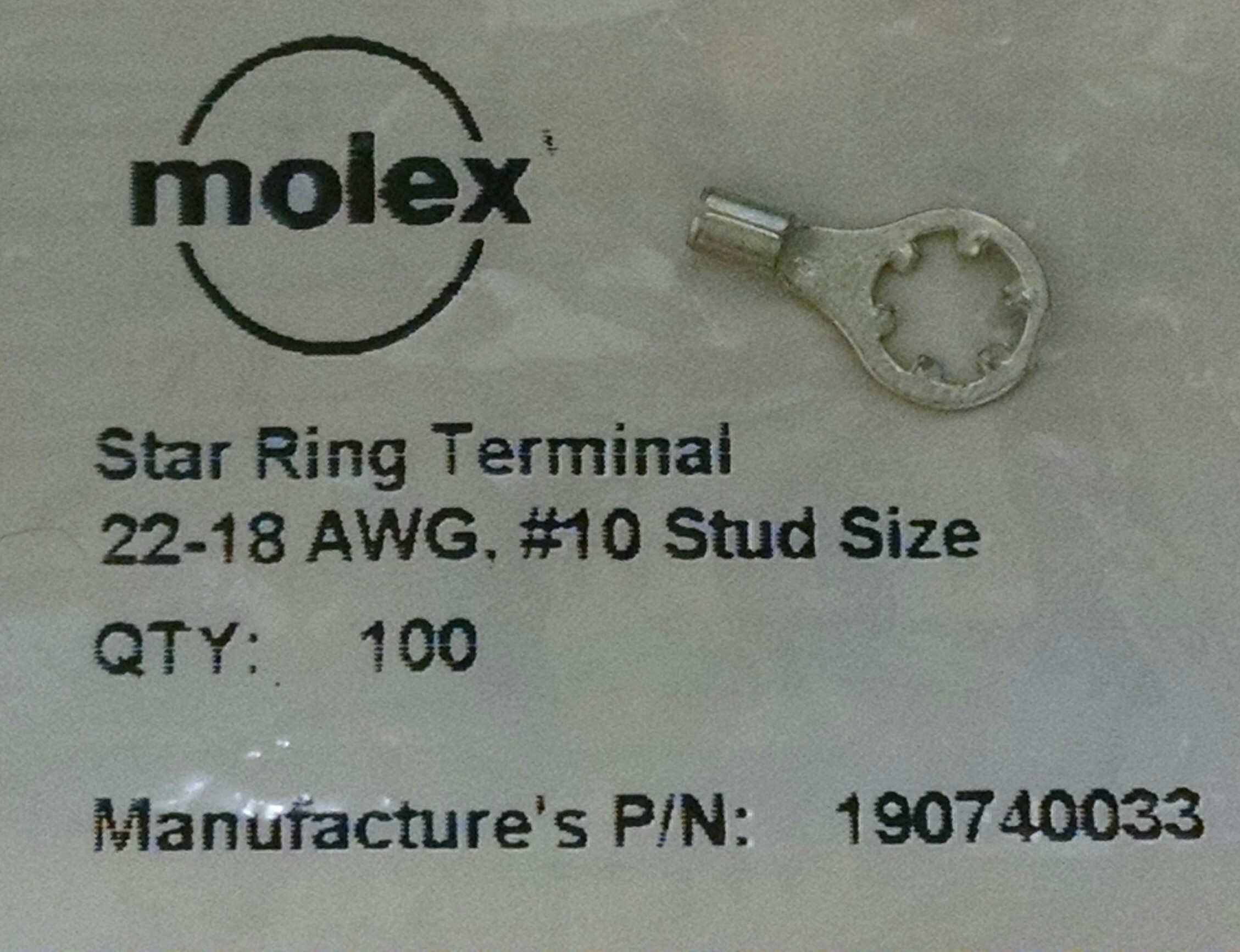
Molex Terminal
The physical connection between the #10 screws on the antenna and the RF connectors is by a Molex star ring terminal, 22-18 AWG #10 Stud, p/n: 1907-40033. found these at the local hardware store.
Soldered to the terminal is a short piece of Belden 83030 Teflon hook-up wire. This is a stranded 19×29, 16 AWG Silver Plated Copper wire ideal for interconnections. The MIL spec rating is 1,000 V, 200°C. All wire is inside the box. When connecting up the lug to the RF connector, use the least amount of wire possible. Loops, or the wire laying against the box forms an inductor or capacitor at VHF frequencies.
SIDEBAR: In keeping with my motto of Quisquam dignitas effectus est dignitas super effectus, you may want to alter your phase line to limit the cost. You could use RG-58, RG-8 or any 50-ohm cable. You need to make your sections of line 1/2 wavelength with propagation factor, internal wiring, and connector length factored in. I used the FSJ1-50 because of its rigidity and ease in mounting to the antenna.
Your phasing line and antenna feed will be an integral part of your antenna. The lines and RF connectors must be able to handle your maximum power. They will also have to be tough enough to stand up to weather. Don’t use bargain-brand electricians tape.
Wrap the entire connection twice with 3M Scotch® Super 88 electrical tape. Then wrap the entire connector twice with 3M Scotch® 2242 rubber electrical tape. Then the last wrap the is twice with 3M Scotch® Super 88. Makes sure there are no gaps, and your layers are overlapped by at least 1/8″.
Start at the box, wrapping around the connector and cable till you get about 1′ to 2″ down your transmission line, then go back to finish the second wraps. Never apply CoaxSeal directly to an RF connector.
Look over your work and make sure there is no way for water to get in. You don’t want to have to take down your antenna to make a repair in the dead of winter, or in the middle of a contest.
ASSEMBLY
Now that the antenna is cleaned up, new hardware is installed, and we have all our parts, let’s shift into the assembly mode. First, we must make some changes to the antenna’s driven element. The screws which presently hold the driven element saddle in place are removed. So are the two screws holding each of the driven elements. We will replace these with #10-24 2.5″ long stainless steel machine screws.
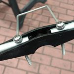
Driven element saddle with elements and hairpin. Image 2 of 2.
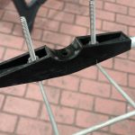
Driven element saddle with elements and hairpin. Image 1 of 2.
The sequence is to put a lock washer on the screw, then a flat washer, and then attach the hairpin to the elements. On the bottom of the saddle you have a flat washer, lock washer, and then a #10 nut. Tighten snug but don’t over tighten and break the saddle.
Next you place another 10-24 x 2.5″ stainless screw through the saddle.
At this point we can attach the feed point.
Before attaching the feed/phasing box, put the following hardware on the threaded ends which will go through the Teflon spacer. A #10 nut, followed by a lock washer, then flat washer. The flat washer will end up against the Teflon. Make sure the nut is down about midway into the mast.
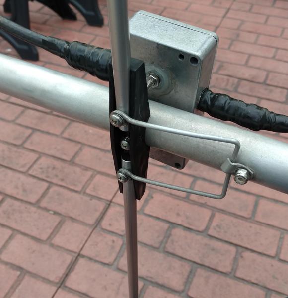
Inside feed box. Input on right, the phasing lines connect to the left connectors.
Attached the feed/phasing box to the mast by the center screw, and then on the inside of the box place a flat washer, lock washer, and nut.
Tighten so the box is solid against the mast.
Be careful not to allow the box to pivot, bending the screws from the driven elements, or damaging the Teflon. Everything should be square.
It’s OK that you have the extra length of the screw in the box. Testing the box with the 2.5″ and a 2.0″ does not show any difference in impedance or performance.
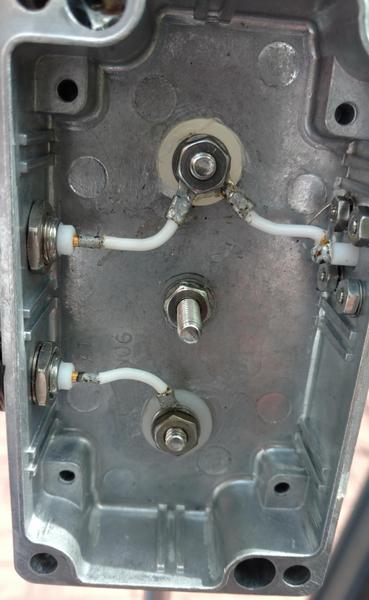
Feed & phasing is mechanically attached by pressure against the Teflon spacers.
Place a flat washer over each screw, then place the lugs over the screws as shown. The right wire is the input to the antenna. The wire to the right of this is the outgoing feed to the phasing line, and the wire below is the return from the phasing line.
Tighten “finger tight” a #10 nut on top of the lug. Here is where it gets interesting.
On the outside of the box, start tightening the nut on the screw till the flat washer is against the Teflon. The tighten the inside. Go back and forth till you have the Teflon wafer equal length inside and outside of the box. You can eyeball it. When done you should have about 1/16th of an inch inside and outside the box. Double check to make sure the hardware is tight. Then you can attach the lid onto the feed/phasing box.
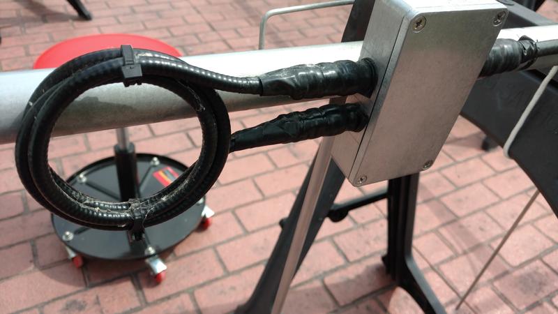
Completed feed/phase box. Phasing line on left.
The box should look like this, with the feed coning in from the right, and the phasing line on the left. The loop I made was scientifically calculated. (humor)
It’s several turns around a can of bee killer spray, with two ty-wraps to hold its shape. and then connected to the box. After connecting everything, use one wrap of Super-88 tape for a courtesy wrap, the rubber tape, and the complete with Super-88. Make sure you mold the rubber against the box. Getting water into the box is not good.
In the image above, you are seeing the box as mounted on the TOP of the antenna. Water should drip down over the box, so before we move on, put some silicone rubber or tub caulk around the edges of the Teflon on the bottom to keep water from somehow getting in.
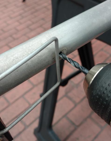
Drill out the tapped screw hole.
#10-24 x 1.50″ to a locknut.
Now let’s fix the hairpin attachment. Remove the screw which held the clamp onto the boom. Drill it out, and drill through to the other side (top) of the mast.
Pass a #10-24 x 1.50″ screw through from the top, and then reattach the clamp with a #10 lock nut. Tighten generously, but don’t crush the mast. This mechanical connection will work better than the old self tapping galvanized screw.
The feed point is now complete! At this point you might want to take some VSWR measurements, or if you’re lucky enough to have a network analyzer you can check to make sure the feed is 50 ohm and the reactance is as close to zero as possible. If you can get somewhere between 47 and 53 ohm, ± 30j, call it good. As you’re testing, bang on the boom while watching the VSWR to check for loose hardware. You don’t want to put an antenna up, only to have to take it down for repair. Check your connections!
The cable feeding my antenna is part of a phasing harness for running two antennas to increase gain. Let’s look at how that’s done.
PHASING TWO ANTENNAS
Phasing two antennas is not that hard. You need 75-ohm cable, (4) Type-N connectors, (1) Type N “T” connector, (1) Type N 90-degree connector, a tape measure, calculator, and some patience.
First, place your antennas where they would need to be. In my case I have two horizontally polarized beams, one over top of each other.
Second, calculate the length of the line. A phasing line for two antennas is an odd wavelength. In other words: ¼, ¾, 1¼, 1¾, 2¼, etc. You also need to know the propagation or velocity factor of the cable. You can find this in the manufacturer’s specifications. But for now let’s assume we’re using RG-11A quad shield. That has a Vf of 0.66. (Sometimes it’s expressed as a %).
FINAL ANALYSIS
I was getting a match of 1.077 : 1.00 at 144.150 mhz. Worse case was transmit at 147.995 mhz which was 1.199 : 1.0. The new matching system worked better than I expected.
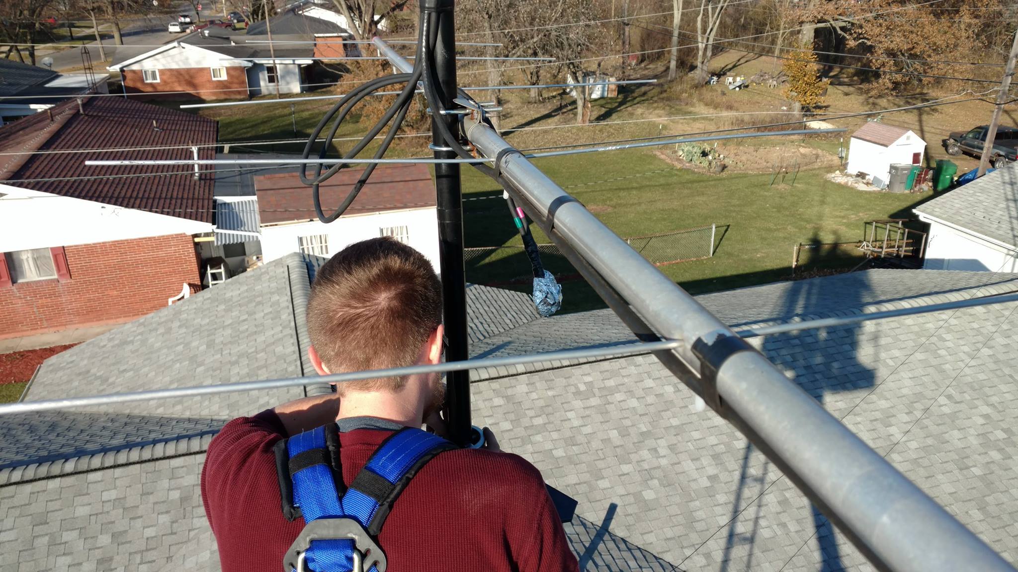
Jon working on Tower
Jon and I had to lift the mast with the two VB-28FM antennas, plus a Diamond V2000A up with mechanical lift. Besides the weight of the antennas and tube (1.500″ OD, 1.2500″ ID, Structural Steel), the total length of the assembly was 26.3′. 6.0′ of the tube went through the thrust bearing to the Ham-IV rotor.
After Jon went through the exercise of properly torquing the bolts, we brought up the rotor control box and checked to make sure it cleanly rotated 360-degrees, and the meter was accurate.
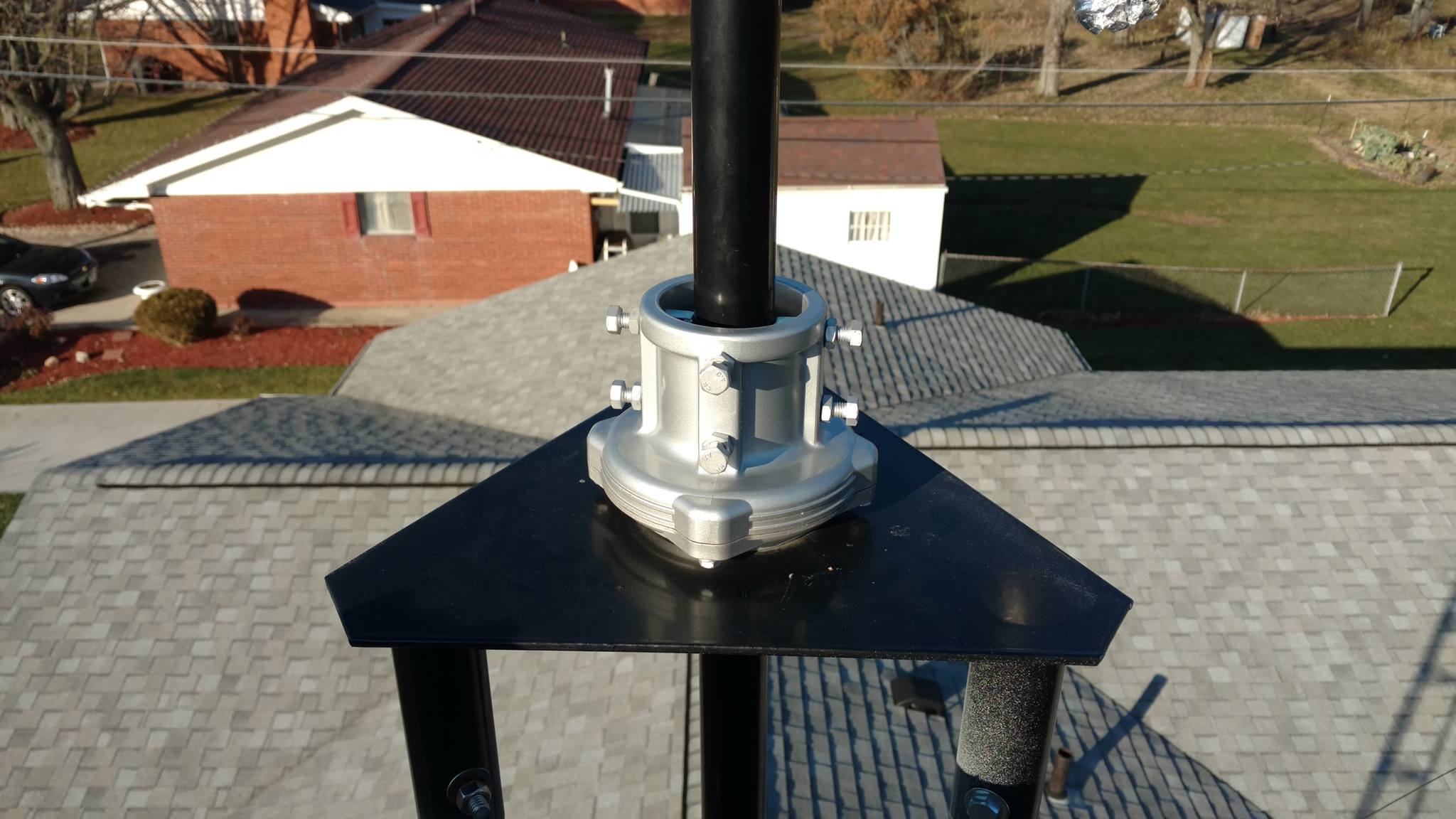 The trust bearing used was a Yaesu model HG-065. The plate you see which the bearing sits on was custom made for the top of the American type 1 tower. (Note American towers do not mate with American type 2 or Rohn 25 towers). Mounting hardware was subbed with Stainless Steel bolts, washers, and nuts.
After making the tower top plate it was taken to Elida Metal Coating company and given an outdoor, thick Power Coating. Black was chosen so in the winter any snow or ice on the plate would receive the maximum amount of warmth from the sun.
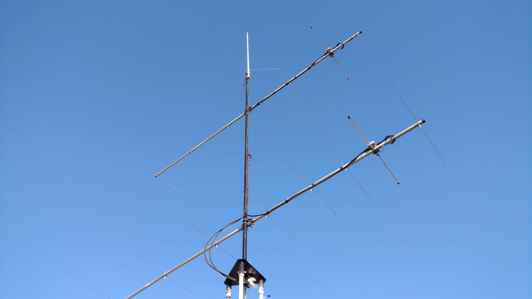 The two VB-28FM antennas are separated by 1 wavelength at 144.1500 mhz. The top VB-28FM did not need any major separation from the Diamond V2000A as analyzer readings showed very minimal inter-reaction in the 2 meter band, and no effect in 6 meters or 70 cm band.
The coax jumpers down to below the top of the tower were RG8/F with Amphenol Type 1, 50? gold pin. They will mate to a panel with Andrew L1PNF-BH connectors which are terminated to Andrew FSJ1-50 transmission line which goes to the room with my ham equipment.
The FSJ1-50 is roughly the same O.D. as RG-6 coax, so I was able to use standard CATV plastic staples to secure the line in the attic. This is a crush-proof type of staple used in cable TV installation.
The transmission line is grounded at the top of the tower just below the top plate, at the bottom of the tower where it transitions into the attic, and then at the RF patch in the radio room. Before the coax enters into the attic it makes 9 loops of roughly 7″ diameter for lighting mitigation.
Analysis of return loss and VSWR over 4 mhz paralleled the readings made on the ground.
One important note… on my Yaesu FT-897D, there is one RF connector for 2 and 70 CM operation. However, 6 meter comes out on the HF connector. This means the feed from the V2000A antenna must go through an RF switch which allow you to select the correct radio port to the antenna.
ROLL YOUR OWN
I have every reason to believe that someone with some time, and ability to work with aluminum could easily built this antenna. Page 2 of the VB-28FM manual provides measurements. However I would advise you build a matcher like I did as the method used by the manufacturer us poor at best.
You should never leave coax open at the end in the outdoors as the capillary action will cause water to migrate up the shield and center conductor. Also, don’t go on the cheap and use at hardware. Spend the money for stainless steel so you get years of uninterrupted use.
__________
NOTES
1). McMaster Carr. http://www.mcmaster.com (330) 995-5500
2). Mouser Electronics. http://www.mouser.com (800) 346-6873
3). RF Parts. http://www.rfparts.com (800) 737-2787
4). Manual for the Hy-Gain VB-28FM in this article. Manual for the larger Hy-Gain model VB-214FM.
5). Diamond V2000A Manual, present manufactured. Use only their hardware as it’s metric.
This article may be linked, reproduced, or distributed without editing and attributing the author.

