The Forgotten “H” Pad

As I work on my home studio I’ve run into level problems in the rack. My rack is not crooked, but my levels are! Anyone who has shot excessive level into an electronic device knows that bad things happen. Most of us don’t always stop to check levels before recording. You patch, hit record, and start recording, only to find out during playback that the recording is distorted.

Levels are measurements in decibels (dB) and be considered either as a power or as a voltage. The level in decibels is 10 times the logarithm of the ratio of two power levels. There are three ways to measure;

  • dBm: decibels or dB referenced to 1 milliwatt (.001 watt)
  • dBu or dBv: decibels or dB referenced to 0.775 volt (dBu is more commonly used)
  • dBV: decibels or dB referenced to 1 volt

I maintain a standard in my home studio of balanced 600-ohm audio at 0 dBu at all inputs/outputs on my patch bay. By doing this I don’t have to change the recording level on the machine based on the source device selected. Some older tube devices have zero reference levels of +4, +8, or +10 dB. I have even seen +12 dB outputs on some old 1940s equipment. The mission is clear. I need to have the level decreased to satisfy my house standard. The solution is the “H” Pad.
Hpad

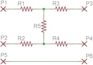
An “H” pad is simply five resistors made in the shape of an “H” laying on its side with the values calculated to achieve a specific loss of signal while maintaining proper impedance. In the case of coming out of a tube compressor with an output of +8 dBu, and needing to have 0 dBu appear at the patch bay, the solution is to calculate for 8 dB of loss.

I hook up the equipment’s output to pins P1, P2, & P5. P1 is +, P2 is -, and P5 is ground.

From the pad, pins P3, P4, & P6, to the patch bay top row. Pin P3 is +, P4 is -, and P6 is ground.

Pad-Bay

What about ground? Without getting into a big debate, I’ve found the most practical solution in high RF/noise areas, and to prevent ground loops, is to float the ground at the output end and attach it at the input. Therefore, all inputs to my patch bay, (top row), are grounded.

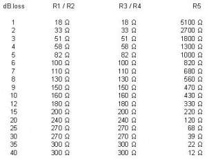
From the chart below, and looking at the schematic of the pad above, we find the values of the resistors.

We need to decrease the level by 8 dB so R1, R2, R3, and R4 are 130-ohm, and R5 is 560-ohm. A caveat here; the assumption is that your output equipment is 600-ohm, and the input of the patch bay is 600-ohm. (Click on the chart to enlarge it and print).

H Pad Values

H Pad Values


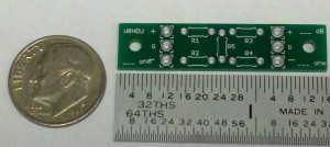
The P.C. Board is very small and measures a whopping 1.50″ (38.1mm) x 11/32″ (8.731mm). It was made small for a reason. It will fit inside of equipment, or inside of a Switchcraft barrel connector. Most of the time I simply attach this to the output, securing the pad to the back of equipment with stand-off posts, and then run a wire to the patch bay.
Pad_PC3

The bottom is where you solder carefully. You need to use a soldering pencil with a very sharp point, thin solder, and solder at approximately 675-700 degrees.

The top of the board has the outline of the resistors. The proper resistors to use would be ones like the Xicon Metal Film Resistors which have a diameter of .07283″ (1.85mm), and a body length of .137″ (3.5mm). Available from Mouser Electronics you would want (4) 130-ohm resistors, and (1) 560-ohm resistors. These would be p/n: 270-130-RC, and 270-560-RC.

The 1/4 watt version of these resistors are tight on the board and one end needs to be raised up, but will work in a pinch. The 1/4 watt versions have a diameter of .0984″ (2.5mm) and length of .2677″ (6.8mm). They would be p/n: 271-130-RC, and 271-560-RC.

Both sides of pad.

Both sides of pad PC Board.


A small hole at each end provides a way to mount the board using a 2-56 screw and spacer, (Keystone p/n: 1797C), also available from Mouser.

Here is a completed 3 dB pad which is ready to be installed. Note the size of the PC Board in relation to the dime.

Complete 3 dB pad

Complete 3 dB pad


This pad will be installed inside the back panel of a tape machine, so the machine remains original spec, but the audio handed off to the patch pay and other equipment is at my required 0 dBu level.

Note: You don’t have to use a PC Board, although it looks better. But if you’re careful, keep your leads short, and use some electricians tape to prevent leads from shorting against the cabinet and other equipment, you can install a pad inside just about anything.

Posted in Building | Tagged , , , , , , , , , , , , , , , , , | 1 Comment

Dual Side Power Supply

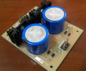
SPS-2b

I recently ran up against a problem where I needed a dual sided power supply for an early 70s piece of equipment. The original manufacturer was out of business, and their PCB was encapsulated in potting solution. All I knew was the main board needed +18 and -18 volts, DC.

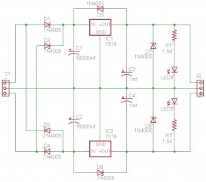
This board is based on the LM340/LM320 or 78xx/79xx series regulator. It can be constructed for +/-5, +/-6, +/-9, +/-12, +/-15, +/-18, or +/-24 volts DC.

As you can see it’s a very simple design using a few diodes, three capacitors, a regulator, resistor, LED, and two connectors for the transformer connection and DC out (if you choose to use connectors).

The project was designed with a slightly more expensive snap-in capacitor because I found this circuit to be very helpful not only in repairing the headphone amplifier, but also my relay switching panel for my amateur radio antenna system, a console project I have been working on, and a switching board that I’m using in our production trailer at work.

The circuit is very simple and I could have breadboard it, but I decided to make up PC boards so it looked professional inside equipment. After all, people judge you by results and the quality they perceive by looks, rather than how clever you can be by using a stryrofoam McDonalds hamburger box for the PCB. The corners are marked for supporting posts, which can be drilled out for (US) 4-40 or 6-32 threads.

SPS-2d

This part list is for the dual 18 VOLT version. Modify as necessary for other voltages. The majority of the parts were found at Mouser Electronics, and can be ordered over the phone or via their web site.

Part List

Part Value     Device           Pkg      Description                                

C1   5,500 f   5985-35V5600     EB30D    Electrolytic Capacitors, Snap In. CDM
                                         Mfgr: Cornell Dubilier 381LX562M035K012

C2   5,500 f   5985-35V5600     EB30D    Electrolytic Capacitors, Snap In. CDM
                                         Mfgr: Cornell Dubilier 381LX562M035K012

C3   1 f       598-SEK010M050ST Radial   Electrolytic Capacitors, 1.0UF 50V
                                         Mfgr: Cornell Dubilier SEK010M050ST

C4   1 f       598-SEK010M050ST Radial   Electrolytic Capacitors, 1.0UF 50V
                                         Mfgr: Cornell Dubilier SEK010M050ST

D1   1N4005    512-1N4005       DO-41    Rectifiers 1.0a Rectifier
                                         Mfgr: Fairchild Semiconductor 1N4005

D2   1N4005    512-1N4005       DO-41    Rectifiers 1.0a Rectifier
                                         Mfgr: Fairchild Semiconductor 1N4005

D3   1N4005    512-1N4005       DO-41    Rectifiers 1.0a Rectifier
                                         Mfgr: Fairchild Semiconductor 1N4005

D4   1N4005    512-1N4005       DO-41    Rectifiers 1.0a Rectifier
                                         Mfgr: Fairchild Semiconductor 1N4005

D5   1N4005    512-1N4005       DO-41    Rectifiers 1.0a Rectifier
                                         Mfgr: Fairchild Semiconductor 1N4005

D6   1N4005    512-1N4005       DO-41    Rectifiers 1.0a Rectifier
                                         Mfgr: Fairchild Semiconductor 1N4005

D7   1N4005    512-1N4005       DO-41    Rectifiers 1.0a Rectifier
                                         Mfgr: Fairchild Semiconductor 1N4005

D8   1N4005    512-1N4005       DO-41    Rectifiers 1.0a Rectifier
                                         Mfgr: Fairchild Semiconductor 1N4005

IC1  7818      512-LM7818CT     TO220    Regulators, std pos, 18V, 1A, 4%
                                         Mfgr: Fairchild LM7818CT

IC2  7918      863-MC7918CTG    TO220    Regulators, std pos, 18V, 1A, 4%
                                         Mfgr: ON Semiconductor MC7918CTG

J1             571-6404523      .100     Flat Header 3P Straight Post tin 
                                         Mfgr: TE Conductivity 640452-3

J2             571-6404523      .100     Flat Header 3P Straight Post tin
                                         Mfgr: TE Conductivity 640452-3

LED1 4300H1LC  606-4300H1LC     T1-3/4   Through Hole RED
                                         Mfgr: Chicago Miniature 4300H1LC

LED2 4300H1LC  606-4300H1LC     T1-3/4   Through Hole RED
                                         Mfgr: Chicago Miniature 4300H1LC

R1   1.5k/8    270-1.5k-RC      Axial    Resistor, 1/8th watt, 1.5k            
                                         Mfgr: Xicon 270-1.5K-RC

R2   1.5k/8    270-1.5k-RC      Axial    Resistor, 1/8th watt, 1.5k 
                                         Mfgr: Xicon 270-1.5K-RC

--   66710ABPP 567-667-10ABPP   Htsink   Heat Sinks TO-220 w/pins  (qty 2)
                                         Mfgr: Wakefield 667-10ABPP

--   4-40x.5   608-R4-40X1/2    Hdwr     Screw, 4-40 1/2" stainless w/washer (qty 2)                           
                                         Mfgr: APM Hexseal R4-40X1/2

--   4-40      534-7248-3       Hdwr     Nut, 4-40 stainless  (qty 2)
                                         Mfgr: Keystone Electronics 7248-3

--   4-40      534-4700         Hdwr     Washer, 4-40, lock-offset   (qty 2)
                                         Mfgr: Keystone Electronics 4700

--   DPS1      DSP1             PCB      Single Side Printed Circuit Board
                                         Mfgr: RealOldiesRadio DPS1
Posted in Building | Tagged , , , , , , , , , , , , , , , , | 5 Comments

Single End Power Supply

SPS-1a
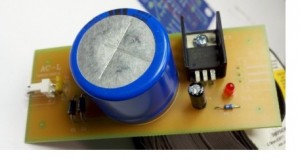
Need a small power supply for a project? This one is based on the LM340 or 78xx series regulator. It can be constructed for +5, +6, +9, +12, +15, +18, or +24 volts DC.

This supply was initially designed for a small headphone amplifier circuit, and LED VU meter driver, but I soon realized it had a lot more applications. As you can see it’s a very simple design using a few diodes, three capacitors, a regulator, resistor, LED, and two connectors for the transformer connection and DC out (if you choose to use connectors).

The project was designed with a slightly more expensive snap-in capacitor because I found this circuit to be very helpful not only in the headphone amplifier, but also my relay switching panel for my amateur radio antenna system, a console project I have been working on, and a switching board that I’m using in our production trailer at work.

SPS-1b

The circuit is very simple and you might as well breadboard it, but I decided to make up PC boards so it looked professional inside equipment. After all, people judge you by results and the quality they perceive by looks, rather than how clever you can be by using a stryrofoam McDonalds hamburger box for the PCB. The corners are marked for supporting posts, which can be drilled out for (US) 4-40 or 6-32 treads. The limitation of this circuit is the capacity of the regulators to carry current. Typically, I don’t like to exceed 750 milliamps of current on these regulators for dependability.

This part list is for the 5 VOLT version. Modify as necessary for other voltages. All parts were purchased from Mouser Electronics, and can be purchased over the phone or on their web site.

  • C1 = .1 uf Capacitor, .1 uf @ 50vdc, 20% (Jameco 25523)
  • C2 = 5,600 uf Capacitor, 5,600 uf @ 35vdc(wv) (Mouser 5985-35V5600)
  • C4 = 1.0 uf Capacitor, 1.0 uf @ 35vdc(wv) (Mouser 647-UMF1V010MDD)
  • D1 = 1N4005 Diode, DO35-10, (Mouser 625-1N4005E-E3/54)
  • D2 = 1N4005 Diode, DO35-10, (Mouser 625-1N4005E-E3/54)
  • D3 = 1N4005 Diode, DO35-10, (Mouser 625-1N4005E-E3/54)
  • D4 = 1N4005 Diode, DO35-10, (Mouser 625-1N4005E-E3/54)
  • AC = L02P Header, Polarized 2P (Mouser 571-6404552)
  • DC = L03P Header, Polarized 3P (Mouser 571-6404553)
  • IC1 = 7805 IC, Regulator, LM340H-05 (Mouser 595-UA7805CKCT)
  • PWR = LED LED, Through Hole, Red, Non-Diff (Mouser 596-SSL-XL0938ID)
  • R1 = 330W Resistor, 330W, ΒΌ watt, metal film 1% (Mouser 271-330-RC)
  • PCB = SPS-1 PC Board only. (HF-Antenna SPS-1)
  • PCB = SPS-1C PC Board Completed. (HF-Antenna SPS-1C)
Posted in Building | Tagged , , , , , , , , , , , , , , | Leave a comment